
Mold production and processing
The process of the mold processing process is very complicated and fine. The mold processing is a profound process. When processing, it is necessary to take every detail seriously and pay attention to the quality of the mold products, so as to produce high-quality molds. The processing flow of DEYING MOULD as follows:
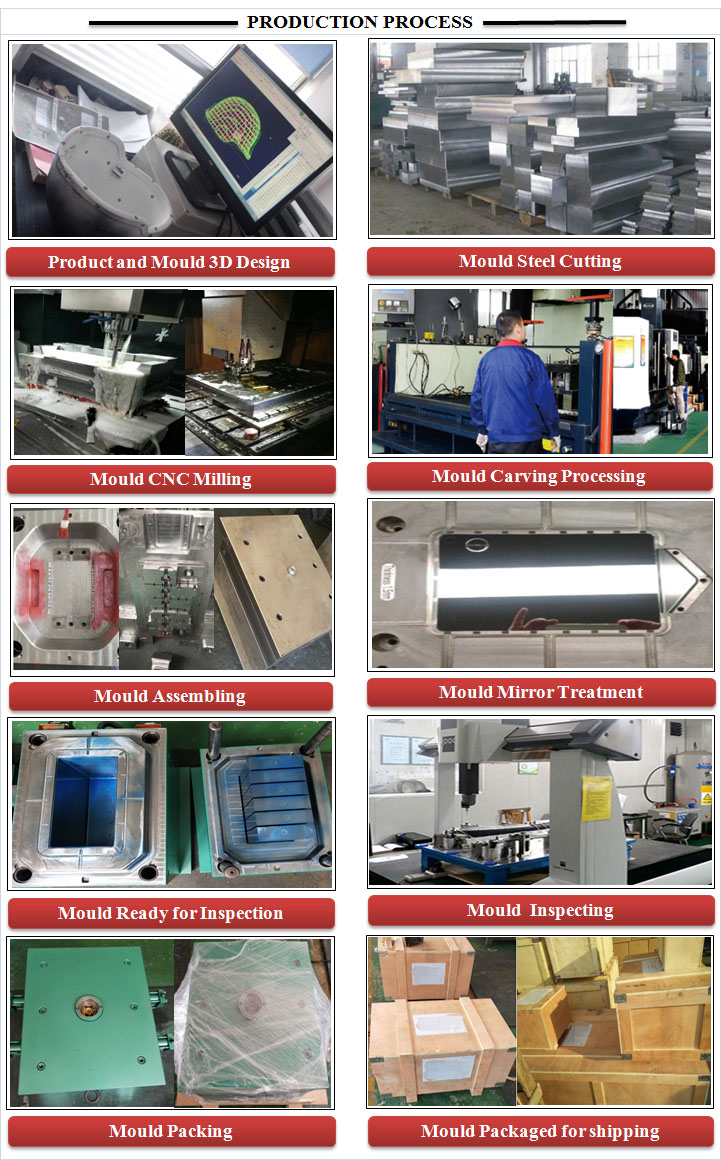
Design
DEYING MOULD will make the design of product and mould based on customer's drawings or physical samples, and then we send design drawings to client confirmation.
Cutting Steel
The customer confirms that the design drawings have no problems, and enters the cutting process of mold steel and related of heat treatment work.
CNC Milling
Mold processing for CNC milling.
Mould Carving Process
Mold processing for carving.
Mould Assembling
After all the molds have been processed, the mold assembly is carried out.
Mould Mirror Treatment
After the assembly is completed, the mold core and cavity are mirrored。
Mould Ready for Inspection and Test
After the core and cavity are assembled, the relevant test of the mold is performed.
Supplier Management
Finding and using the right industrial suppliers for the job is a critical part of the production process. Using the wrong type of tool steel, for example, can be disastrous. The cheapest is certainly not always the best.
We evaluate the suppliers according to their performance
♣ Know-how of the job/product
♣ Trial order of small quantity for test
♣ Consistency for delivery & quality for bigger quantity.
Only those who pass the evaluation will be chosen to work with together. It’s an critical important process for mold making and to get the project done successfully.The main of our supplier as follows:
1、Mold Steel Supplier

2、Mold Hot Runner Supplier

3、Mold Base Supplier

4、Standard Parts Supplier

5、Plastic Material Supplier
6、Texture Supplier
Mould Design Checklist
Below is a simple injection mold design checklist which is an essential tool for us, including a vast number of details in injection mold making, making sure that all components are fit, the dimensions work together and that the mold will ultimately function as it should. We recommend every client also confirm the 3D mold drawings according to some similar checklists.
| - clamping situation |
NG |
OK |
NO NEED |
Remark |
|
|
1 |
Max. Mold height | ||||
|
2 |
mold installation height | ||||
|
3 |
overlaid clamping plate | ||||
|
4 |
clamping slots- holes | ||||
|
5 |
locating ring diameter | ||||
|
6 |
centering ring MS | ||||
|
7 |
nozzle installation depth | ||||
|
8 |
heating band and cabel slot for injection machine enough | ||||
|
9 |
ejector pin according to customer’s requirement. | ||||
|
10 |
label (hot channel,cooling schema,company label) | ||||
|
11 |
transport bridge/tie bar – Transport thread – Transport protection | ||||
|
12 |
insulation sheets MS / FS | ||||
|
13 |
hot channel connector on the top of non operator side | ||||
|
14 |
cooling connector don’t interrupt clamping process | ||||
| - mold assembly | |||||
|
16 |
sufficient mold plate thickness | ||||
|
17 |
countour with insert | ||||
|
18 |
countour in moldbase | ||||
|
19 |
the angle of wedge is 5 degree by milling designed | ||||
|
20 |
nozzel radius R mm | ||||
|
21 |
ejector plate guidance | ||||
|
22 |
support pillars in the ejector room. | ||||
|
23 |
enough ejection stroke | ||||
|
24 |
return pin | ||||
|
25 |
locking for side pressure | ||||
|
26 |
slide locking on the mold plate is one unit | ||||
|
27 |
angular pin diameter enough | ||||
|
28 |
ejector system switch | ||||
|
29 |
support legs | ||||
|
30 |
pressure plate for parting surface | ||||
|
31 |
parting line on the mold plate?(if mold on the plate ) | ||||
|
32 |
Hydraulic connector according to customer’s requirement. | ||||
| - inserts and slide | |||||
|
33 |
Material according to Specification | ||||
|
34 |
the mount and position of ejector pins/ fixed.. | ||||
|
35 |
venting slots or inserts | ||||
|
36 |
set limit switch for ejector, which under the slide | ||||
|
37 |
label according to customer’s standard (demountable) cavity label | ||||
|
38 |
enough slide stroke | ||||
|
39 |
slide fixture. (ball guiding-slide lock) | ||||
|
40 |
lifter wearing blocks are made of Bronze / Steel | ||||
|
41 |
insert cores for ribs and hooks | ||||
|
42 |
area/shape of the parting line | ||||
|
43 |
long core or inserts locked from the opposite direction. | ||||
|
44 |
parting line free milled enough. | ||||
|
45 |
guide pin is longer than angular pin | ||||
|
46 |
oil slot on slide and angle slide | ||||
|
47 |
angle slide lower than the mold surface.(no scratchs on the surface) | ||||
|
48 |
if use angle lifter, ejector plate intensity is enough( thicken the ejector plate?) | ||||
|
49 |
pressure plate for slider sink into mold plate 3-5mm.(if not ,add dowel pin) | ||||
|
50 |
for angle slider,pressure plate and wearing plate is one inte | ||||
|
51 |
slider extend into cavity, assemble surface 3°-5°degree diving | ||||
|
52 |
use graphite as wearing plate for big slider. | ||||
|
53 |
slider easy to assemble and disassemble. | ||||
|
54 |
material stick slider and angle lifer. | ||||
|
55 |
parts can drop automaticly or need to use robot when there is anglelifer | ||||
|
56 |
angle lifter has fixing plate( in the middle) | ||||
|
57 |
processing basic point and sealing even surface for angle lifter, | ||||
| - gate system | |||||
|
58 |
cold runner length and gate bar diameter. | ||||
|
59 |
hot nozzel | ||||
|
60 |
hot channel | ||||
|
61 |
needle valve | ||||
|
62 |
brand according to customer’s requirement | ||||
|
63 |
direct connection | ||||
|
64 |
tunnel gate (baffle) with cold channel spread. | ||||
|
65 |
enough tunnel diameter | ||||
|
66 |
bent gate | ||||
|
67 |
auxiliary tunnel gating | ||||
|
68 |
spheriacl calotte (沉头) | ||||
|
69 |
gate cross-section round / trapezium | ||||
|
70 |
changeable gate inserts | ||||
|
71 |
gates / parts fall freely | ||||
|
72 |
sprue puller (undercut) | ||||
|
73 |
Is the Position of injection point right | ||||
|
74 |
monifold as short as possible | ||||
|
75 |
balanced flow path | ||||
| - Tempering | |||||
|
76 |
connectors according to customer’s requirement. | ||||
|
77 |
the number of cooling cycles. | ||||
|
78 |
diameter of cooling holes are big enough | ||||
|
79 |
mold plate temper | ||||
|
80 |
insert temper | ||||
|
81 |
slide temper | ||||
|
82 |
hot nozzel off cold runner | ||||
|
83 |
cooling connector (under/opposite the operator side) | ||||
|
84 |
calculate injection cycle time : ……………….. realizable | ||||
|
85 |
cooling in/outlet mark start form A plate to B Plate from bottom to top | ||||
|
86 |
mini.distance between 2 cooling connectors is 25mm | ||||
|
87 |
mini.distance between cooling hole ,screw hole, ejetor and ejector hole 4mm | ||||
|
88 |
same distance between cooling line and products in ejector and nozzle side | ||||
|
89 |
cooling line as short as possible | ||||
| Some more check points |
NG |
OK |
NO NEED |
Remark |
|
|
1 |
products including shrinkage | ||||
|
2 |
products mirror reflection | ||||
|
3 |
guide pillar ,screw, support pillar, ejector guide bush and locating ring same as drawing | ||||
|
4 |
inserts dimension and depth no different from drawing . | ||||
|
5 |
cooling system and ejector pin don’t interrupt each other | ||||
|
6 |
cooling system and screw don’t interrupt each other | ||||
|
7 |
cooling don’t interrupt insert | ||||
|
8 |
O ring , screww and ejector pin don’ t interrupt each other | ||||
|
9 |
cooling system and screw holes for lifting bar don’t interrupt each other | ||||
|
10 |
side lock , cooling system and screw don’t interrupt each other | ||||
|
11 |
lifting bar and junction box don’t interrupt each other | ||||
|
12 |
lifteing bar and junciton box don’t interrupt each other | ||||
|
13 |
limit switch , return pin and screw don’t interrupt each other | ||||
|
14 |
ejector pins and angle lifer don’t interrupt eachother | ||||
|
15 |
straight clamping slots and locking unit screw don’t interrupt eachother | ||||
|
16 |
ejector pins and support pillars don’t interrupt each other | ||||
|
17 |
ejector sleeve and ejector rod don’t interrupt each other | ||||
|
18 |
mark spring type clearly | ||||
|
19 |
thick pillars for screw and thick ribs cut material | ||||
Mould Trial Checklist
Every mold has been tested for at least 2 hours on the IMM to make sure the performance for mass production. We will take notes of the parameter for mold trials.
| Mould Name: | Cover 1 Mold | Product Weight: | 13g | |||||
| Cylinder Temperature By Zone | ||||||||
| First Paragraph | Second Paragraph | Third Paragraph | Fourth Paragraph | Fifth | ||||
| 240 | 315 | 320 | 318 | 210 | ||||
| Hot Runners Temperature | ||||||||
| Manifold | 240 | |||||||
| Nozzles | 260 | 258 | ||||||
| Injection Parameters & Profile: | ||||||||
| Injection Speed:% / MM /SEC | 75 | 25 | ||||||
| Pressure:(Bar) | 80 | 35 | ||||||
| Injection Time:(SEC) | 0.6 | Cool Time(SEC): 3 | ||||||
| Follow Up Pressure | ||||||||
| Pressure(Bar) | 40 | |||||||
| Duration | 0.5 | |||||||
| Cycle Time:(SEC) | 14 | |||||||
| Machine Status | ||||||||
| Automatic | / | Semi Automtic | √ | |||||
| Mould Temp/Air Parameters | ||||||||
| Cavity Side | Core Side | |||||||
| Temperature | 65 | 60 | ||||||
| Air Ejection | / | / | ||||||
| Raw Material | ||||||||
| Name | Flow Rate | Shrinkage | RE: | |||||
| PP | 25 | Powder Material | ||||||
Final Mould Checklist
Every mold has to be checked before shipment to make sure everything is made correctly and the mold is ready for production on client’s machine.Here are some main points to be checked
| Item |
Checking details |
Yes |
No |
Remark |
|
Mold Appearance |
1. No rust on any plate and grease applied for protection | |||
| 2. All mold plate edges are properly chamfered | ||||
| 3. Project No. and part No. is applied on every part | ||||
| 4.Logo and name plate is fixed according to request | ||||
| 5.No scratches or damages and mis-drilled holes | ||||
| 6. Number for cooling nozzles and in-out water is clearly marked below the nozzle or at the right side of the nozzle, e.g.:IN1 OUT1 | ||||
| 7. Nozzles for oil or air is clearly marked with in & out, with A in front for Air, and O in front for Oil. | ||||
| Parting surface | 1.No mark for polishing on parting surface | |||
| 2.No mark for polishing on non-sealing surfaces | ||||
| 3. No collapse for shut-off and kiss-off parts. | ||||
|
Cavity |
1. check if there is any parts not processed according to 3D drawing | |||
| 2. no mark for welding in cavity (un-confirmed welding) | ||||
| 3. check for several surfaces after CNC machining | ||||
| 4. check for several surfaces after EDM processing | ||||
| 5. cavity is smooth, no scratches, no EDM marks, and blade marks. | ||||
| 6. polishing at the rib is towards the ejection side | ||||
|
Inserts |
1. inserts fit well, neither loose nor too tight. The surface is smooth after putting inserts | |||
| 2.If there are some changible insrts, easy to change? | ||||
| 3.no cushion at the bottom of the inserts | ||||
| 4.chamfer at the bottom of inserts is smooth and no chamfer for bottom cooling water nozzles | ||||
| 5. polishingn is fine for inserts? | ||||
|
Slider |
1.slider is processed according to the tolerance agreed | |||
| 2.slider is workign smoothly, not blocked or shaking | ||||
| 3.the positioning of the slider is reliable and processed accoding to 3D drawings. | ||||
|
Lifter |
1.no scratches on the surface where the lifter is located. | |||
| 2.lifter can work smoothly? | ||||
| 3.polishing for surface where the lifter is positioned is ok? | ||||
|
Ejection system |
1.The ejector plate can move smoothly without stucking anywhere. | |||
| 2.Every ejector pin can be put into the hole for assembly easily, turned easily, without shaking | ||||
| 3. No chamfer for ejector hole, and the wall for the hole is smooth | ||||
| 4. the ejector length is to be processed within dimension tolerance. | ||||
| 5.support pillar is 0.05-0.10mm higher than mold feet. | ||||
| 6. air ejection path is clean? no oil or metal scraps? ejection is smooth? | ||||
| 7. oil ejection path is clean without metal scraps? ejection is smooth? | ||||
|
Cooling system |
1. cooling water path is clean and made according to the 3D drawing? | |||
| 2. O-rings is reliable without leakage? | ||||
| 3. thread for water nozzle is made according to client’s request? | ||||
| 4. baffle is assembled correctly? | ||||
| 5. seal groove is smooth? |
Mould Component Process Service
DEYING Mold Components: Focusing on the Precision and the Seamless Fit with Mold
DEYING can provide customers with high precision mold components according to precise requirements of customers, including core, insert, insert core, slide, guide bush, active core module, locating pillar, safety strap, SKH-51 and SKH-61 serial ejector sleeve, ejector pin and sprue puller, widely used in plastic mold, automobile mold, medical mold, semiconductor mold and automation industry, seamlessly fitted with customers' mold, so manufacturing cost and cycle can be greatly saved.
DEYING focuses on manufacturing mold components with complex shapes and requirements of high precision. Due to complex shape and rich details, high precision is required. Even at the micro level, MBA can guarantee absolute accuracy: ±0.001μm~±0.005μm. In the past, we mainly engaged in EDM and linear cutting. However, if these traditional methods are used in particularly hard materials, the accuracy will be reduced by the cracks caused by discharge. In order to achieve lasting durability, DEYING uses high-precision machining, such as milling, even if it takes longer and is more expensive. A kind of particularly complex mold component is with rounded cusp which needs great technical knowledge. Each of our technicians has technical specifications and equipment required. DEYING has established a high reputation among our customers in complex components.
According to the export mold standard like European and American standard, DEYING can process mold components well according to customer's drawing. Our engineers will also assist clients to assemble components.
DEYING mold components design provides the thermal uniformity which is necessary for all thermoplastic resin precision molding; thermal distribution of insulation or hot runner can be selected, and optimum efficiency can be obtained by selecting the corresponding system.
1. Precise dimensions. All mold components are machined, by combining with CNC turning and precision grinding to reduce the size tolerance. Before shipment, using 3D coordinate measurement so that each component will undergo a strict final inspection.
2. High-quality raw materials. All standard components are processed into a hardness of 54-56RC from AISI H13 tool steel. Additional grades of tool steel and special coatings can also be provided to meet the special requirements of glass and mineral filled resins.
3. The best Heat Profile. All components are in thermal coordination with the processing environment. All mold components are designed considering the temperature uniformity in the manufacturing process, and they will be tested in the actual mold environment to meet our stringent standards.
After receiving orders, we will decide the right procedure. According to 3D data or drawings of products, MBA will select technical personnel and processing methods, consider technical requirements such as dimensional tolerances and optimize manufacturing conditions.
DEYING provides the highest accuracy and quality for our customers and keeps the promised delivery date.